We are five engineering students from Catalonia’s Polytechnic University, willing to learn about Arduino. This blog has been created in order to show our moves inside this interesting world. Therefore, we will share our improvements in programming and in using the wide range of available elements (servomotors, switches…) Arduino’s Starter Kit offers, while making small projects. Each one will represent something new, so we wish we can also have the chance to help other Arduino’s beginners.
This blog will be structured in two parts: the first one will consist in sixteen projects (divided into two blocks, eight projects per block) to learn about how does Arduino work. We will carry out the projects (all of them described in the Starter Kit’s book), but also make little changes to them. And don’t worry, it will all be explained! The second part will consist in a practical application of the knowledge acquired, a creative project we will make on our own, perfectly described too.
And now, we just want to say we are so grateful to take part of this adventure and that we hope to involve our readers too, so let’s start!
It’s been almost a year since we started the blog, however, we missed the opportunity to post about what we got to build at the end of our class with Arduino.
Therefore we are going to publish this post, which will probably be our last, following through our promise and linking to the pdf of the draft of our project.
Even after almost a year later, the members of the team (pictured in the About us section) all agree that working with Arduino was a great experience. We got to learn first-hand about many little details involved in electronics and programming. The best about Arduino is that when you’ve managed to learn the basics, the next step is up to you to tinker and build complexer systems that do really cool stuff!
So, to everyone out there deciding whether or not to face the challenge of building with Arduino, we encourage you to do so.
If there’s anything with which we can help you, don’t think twice and send us a message or leave a comment below and we will be willing to answer, we’ll keep checking the site every once in a while.
This is the last project in the Arduino Starter Kit. We hope you enjoy it!
Before starting you must know that in this project a button is going to be hacked. This button can be from whatever electronic device which has one. In this post, the explanations are referred to a digital recording module which records and play back sound.
CAUTION: you must know that whatever device you use, when hacking it, you will lose de device’s warranty.
That’s why our team has decided not to build this project. Notwithstanding this, everything is going to be properly-explained as in all the previous posts.
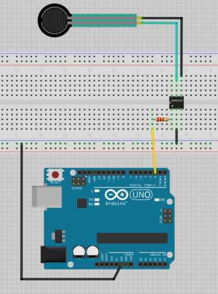
Hacking a button means that Arduino will press the button instead of having to do it manually by someone. To this end an optocoupler will be required to make the circuit. As you may well know, optocouplers are integrated circuits that allow to control another one without any electrical connection between both.
In order to make the properly connections, the following image will help you. If it’s possible, try to do it without soldering any wires.
When making the connections with the electronic device be careful and do exactly what we say here. First of all, look for the playback button and remove it from the recording. Under this button are two small metal plates. These are the two sides of the switch and they get connected when pressing the button.
In this case, as anyone is going to press it, you should connect one wire to each of the small metal plates in order to connect them to the optocoupler (do it exactly as it is shown in the previous picture). We recommend to do it using tape instead of soldering.
After making all the required connections, it’s time to do the code. As always, all the steps are perfectly explain below. Is to notice that there is no particular difficulty in this program.
//Naming a constant for the optocoupler control pinconstintoptoPin=2;voidsetup(){//Setting the optocoupler as an OUTPUTpinMode(optoPin,OUTPUT);}voidloop(){//Pulling the optoPin HIGH for a few milliseconds. Time enough to close the switch's device.digitalWrite(optoPin,HIGH);delay(15);//Pullong the optoPin LOW for 21 seconds, then the recording will start again.digitalWrite(optoPin,LOW);delay(21000);}
To execute this project you must record a 20 seconds (or less) sound. Afterwards, power the Arduino with the USB cable. The recording should start to play and a few momentss after finishing, it should start again.
A video which exemplifies this project is the following. Notice that is not recorded by our team and in this case a LED is being hacked instead of a recorder. Anyway, we hope it helps you.
And now is time to think about what would you like to create with Arduino. Your ideas could change our lifes. So please, don’t heasitate and start realizing them.
Hi everyone! Welcome to our new post. We hope you are enjoying the Arduino Starter Kit Projects. You should know that they are about to finish. Nevertheless, don’t feel melancholy; in fact, a wonderful project is bound to start. But let’s begin with this new project called Tweak the Arduino Logo.
What is this project about? In this case serial communication is going to be used to control a program on your computer with your Arduino. As you may know, when programming in Arduino, a connection between the computer and the microcontroller is opened. On this project, this connection is going to be used to send data back and forth to other applications.
Thanks to serial communication, your Arduino and your PC will exchange bits of information. Is important to notice that to successfully establish this communication the speed they exchange information must be the same. So that, we will get values from the analog inputs and use them into a program written in a different environment: Processing. Don’t worry it is similar to Java and Arduino as well. However, you can start familiarizing with Processing looking at some useful tips here: Getting Started.
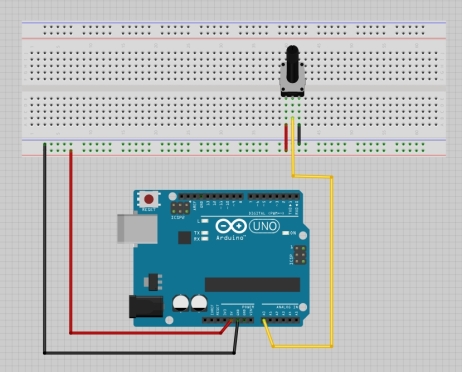
In order to tweak the logo, the analog inputs will be proportionated by a potentiometer. So, in this case, the circuit in your Arduino is as simple as that:
Furthermore, you must install in your computer Processing – just click here to install the last version (3.0.2) of this software,the same as we have used.
In this case, we should write two codes, one in Arduino and another in Processing. Pay attention to the explications made below. And ask us if there is any doubt.
The code in Arduino is:
voidsetup(){// starting serial communication. Make sure Processing and Arduino have the same serial baud rate.Serial.begin(9600);}voidloop(){// Sending to the serial connection the analug inputs introcued by the potentiometer.// As only is possible to send values from 0 to 255, devide de AnalogRead value by 4.Serial.write(analogRead(A0)/4);// After sending the byte, let the ADC stabilize.delay(33);}
And in Processing:
//including the serial ports external lybrary
import processing.serial.*;Serial myPort;
//Creating an object for the image
PImagelogo;
//Creating a variable to store the background colour
intbgcolor=0;void setup(){
//Setting the colour mode. In this case we're useing HSB(HueSaturationBrightness). The hue will change while turning the potentiometer.
colorMode(HSB,255);
//loading the image directly form the Internet
logo=loadImage("http://arduino.cc/logo.png");
// you can use "size(logo.width,logo.height)" to automatically adjust the scale
//if you have problems, adjust it manually:
size(170,120);
//Printing a list with all the serial ports your computer has when the program first starts.
println("Available serial ports:");printArray(Serial.list());
//Telling Processing information about the serial connection. The parameters are: which application will be speaking to, which serial port will be communicating(depending on the previous result), and at what speed.
myPort=newSerial(this,Serial.list()[0],9600);
}
//Analog function to void loop() in Arduino
voiddraw(){
//Reading Arduino data from the serial port
if(myPort.available()>0){ bgcolor=myPort.read();println(bgcolor); }
//changing the image background
background(bgcolor,255,255);
//Displaying the image and starting drawing on top left (0.0)
image(logo,0,0);
}
If executing this program, the result should be the following:
Now it’s time to use your imagination. Some cute variations are:
Changing the Arduino logo by a heart. You just have to change the URL for a new one.
Replacing the potentiometer by a photoresistor. In this case, the colour will be changing depending on the light.
In this project the main objective is to control the states of a lamp with a sensitive mode.
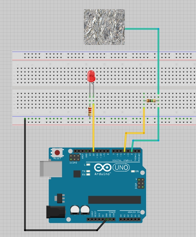
We will use a led, two resistors (1 MOhm and 220 Ohm) and a metal foil. In our experiment the metal foil will be the touchy-detector and the led will act as a lamp.
First of all, we will have to set up the electrical circuit to continue with the project. In the image we can see how to connect the elements:
As we can see, there’s no line connected to 5V. The reason is that we will use a library in the code which will allow us to create a capacitor from two pins and 1 MOhm resistor, avoiding us to provide a 5V potential difference from the Arduino Board.
The following step will be to write the Arduino code and implement it on the board.
//Import a library from the Arduino folder#include <CapacitiveSensor.h>//Select the two pins that will act as a capacitor
CapacitiveSensor capSensor = CapacitiveSensor(4,2);//Insert the minimum value provided by the sensor to detect the touch
int threshold = 1000;
const int ledPin = 12;
voidsetup() {Serial.begin(9600);
pinMode(ledPin, OUTPUT);
}
voidloop() {
//Read the sensor value
long sensorValue = capSensor.capacitiveSensor(30);
Serial.println(sensorValue);
//Touch detected
if(sensorValue > threshold) {//Turn on the led
digitalWrite(ledPin, HIGH);
}//Touch undetected
else {
//Turn off the led
digitalWrite(ledPin, LOW);
}
delay(10);
}
We have used a new library to write the function: CapacitiveSensor.h. It has been implemented to help us and simplify the code.
Here is a demonstration of how it works:
To brush up some concepts acquired in the projects made before, we have created a thief detector using a buzzer, a led and the capacitive sensor executed before. We have designed this function to detect if a thief is trying to break into our home. The sensor has to be put in the door, and the led and the buzzer have to be installed in an habitated room. Here you have a video of the variation made:
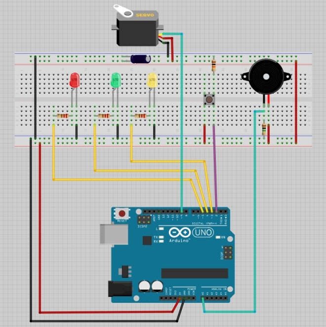
In this project we’ll build our own lock system that only can be unlocked by knocking 3 times.
For this project we need 3 different colour Led, some resistors, a switch, a capacitor and a servomotor.
By pressing the button the system will get locked, which will be indicated by the red LED. The knocks will be captured by the buzzer (remember that the buzzer can act like a speaker and a vibration sensor), and each time it detects a knock, the yellow LED will blink once. When we had knocked 3 times, the servomotor will turn 90º and the green led will be on. Indicating that the system is unlocked.
We will know the current state of the system because it will be displayed (if it’s un/locked, knocks left…).
We need to connect our buzzer to an analogic pin, due it generates a wide data range, not only 1 or 0.
The 3 LED’s will be connected to digital outputs, and the signal pin of our servomotor will be connected to a digital pin too. But remember to connect it to pin that can act like an analogic output trough PWM (as seen on previous projects).
The capacitor’s function is to stabilize the electric signal.
The main objective of the program is to turn 90º the servomotor and turn the red light on when the button is pressed. Then, it will start the knock countdown. Each time the buzzer detects a knock the yellow light will blink. When the system has detected 3 knocks will return the servo to its natural position and turn the green light on.
// import the library
 #include <Servo.h>
 // create an instance of the servo library
 Servo myServo;
const int piezo = A0;
const int switchPin = 2;
const int yellowLed = 3;
const int greenLed = 4;
const int redLed = 5;
//defines LED's and piezo's pins.
// variable for the piezo valueint knockVal;
// variable for the switch valueint switchVal;
// variables for the high and low limits of the knock valueconst int quietKnock = 10;
const int loudKnock = 100;
// variable to indicate if locked or notboolean locked = false;
// how many valid knocks you've receivedint numberOfKnocks = 0;
void setup(){// attach the servo to pin 9myServo.attach(9);
// make the LED pins outputs
pinMode(yellowLed, OUTPUT);
pinMode(redLed, OUTPUT);
pinMode(greenLed, OUTPUT);
// set the switch pin as an input
pinMode(switchPin, INPUT);
// start serial communication for debuggingSerial.begin(9600);
// turn the green LED on
digitalWrite(greenLed, HIGH);
// move the servo to the unlocked positionmyServo.write(0);
// print status to the serial monitor
Serial.println("the box is unlocked!");
}
void loop(){
// if the box is unlockedif(locked == false){
// read the value of the switch pin
switchVal = digitalRead(switchPin);
// if the button is pressed, lock the boxif(switchVal == HIGH){
// set the locked variable to "true"
locked = true;
// change the status LEDs
digitalWrite(greenLed,LOW);
digitalWrite(redLed,HIGH);
// move the servo to the locked positionmyServo.write(90);
// print out statusSerial.println("the box is locked!");
// wait for the servo to move into positiondelay (1000);
}
}
// if the box is lockedif(locked == true){
// check the value of the piezo
knockVal = analogRead(piezo);
// if there are not enough valid knocksif(numberOfKnocks < 3 && knockVal > 0){
// check to see if the knock is in rangeif(checkForKnock(knockVal) == true){
// increment the number of valid knocks
numberOfKnocks++;
}
// print status of knocksSerial.print(3 - numberOfKnocks);
Serial.println(" more knocks to go");
}
// if there are three knocksif(numberOfKnocks >= 3){
// unlock the box
locked = false;
// move the servo to the unlocked positionmyServo.write(0);
// wait for it to move
delay(20);
// change status LEDsdigitalWrite(greenLed,HIGH);
digitalWrite(redLed,LOW);
Serial.println("the box is unlocked!");
}
}
}
// this function checks to see if a // detected knock is within max and min range
boolean checkForKnock(int value){
// if the value of the knock is greater than // the minimum, and larger than the maximumif(value > quietKnock && value < loudKnock){
// turn the status LED ondigitalWrite(yellowLed, HIGH);
delay(50);
digitalWrite(yellowLed, LOW);
// print out the statusSerial.print("Valid knock of value ");
Serial.println(value);
return true;
}
// if the knock is not within range
else {
// print statusSerial.print("Bad knock value ");
Serial.println(value);
return false;
}
}
Once coded and assembled everything is time to check our knock lock system out.
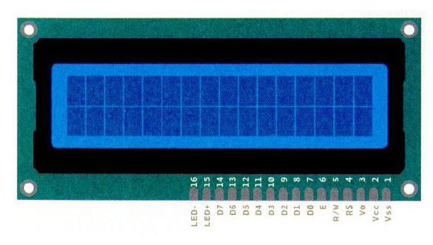
In this project we learnt to deal with a Liquid Crystal Display, known better by its abbreviation to LCD. Although the LCD is connected to various signals as it receives different type of information, there is already an available Liquid Crystal Library which makes it easier to configure and control the characters displayed on the screen without dealing with low-level basics of how the screen actually works.
The screen has up to 16 pins, ranging from digital pins to power supplies (Vcc, Vss, LED+-, etc.). The R/W sets up if the panel should be used to write or to read. Pin number 6, or E warns when it is to receive an instruction. Pin number 3 sets the luminosity of the screen.
The creative part of this project consisted in using the screen as a fortune teller. If we turn the breadboard upside down, the screen will search between its answers a random one and display it onscreen. The potentiometer regulates the luminosity.
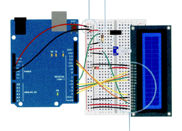
We assembled this circuit:
#include<LiquidCrystal.h>LiquidCrystallcd(12,11,5,4,3,2);// generates an instance
in the lcdconstintswitchPin=6;intswitchState=0;intprevSwitchState=0;intreply;
voidsetup(){lcd.begin(16,2);pinMode(switchPin,INPUT);lcd.print("Preguntame");lcd.setCursor(0,1);// changes the Cursor to continue
writing in the second rowlcd.print("Bola de Cristal");}
voidloop(){switchState=digitalRead(switchPin);if(switchState!=prevSwitchState){if(switchState==LOW){reply=random(8);lcd.clear();// clears the writinglcd.setCursor(0,0);lcd.print("La bola dice:");lcd.setCursor(0,1);switch(reply){// the program will enter the case
assigned to the switchcase0:lcd.print("Si");break;case1:lcd.print("Es probable");break;case2:lcd.print("Ciertamente");break;case3:lcd.print("Buenas perspectivas");break;case4:lcd.print("No es seguro");break;case5:lcd.print("Pregunta de nuevo");break;case6:lcd.print("Ni idea");break;case7:lcd.print("No");break;}}}}
On the previous project we got acquainted with motors and transistors in Arduino. However, until this unit we were not able to control the direction in which the motor spinned without manually swapping the ground and power wires. This activity aims to learn this new ability. To do this, we must first explain a fundamental element : the H-Bridge
To learn the following we had to do a little research ourselves, and we found this page to be quite of help. Things will get a little technical for a moment, so if you don’t want to deal with this, you can skip to a later brief summary.
As explained, a motor will spin clockwise or anticlockwise depending on the direction of current flow, which is imposed by the voltage across its terminals . We want to be able to control the direction of current to direct the spin of the motor.
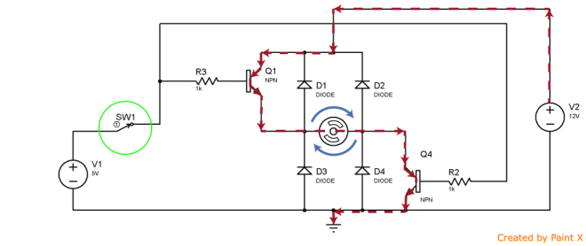
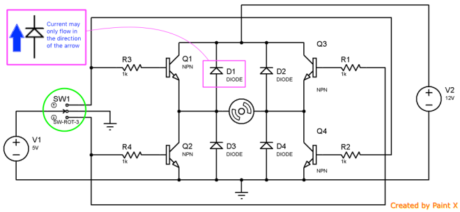
The next scheme illustrates an electrical circuit of an H-bridge, similar to how the Arduino one might work.
Notice that this scheme has 5 components: resistors, diodes, transistors, the motor and two voltage sources. In this circuit current doesn’t flow in any direction, because the switch highlighted in green is open. Current doesn’t move across the resistors that are connected to the transistor’s gate. The transistors, which act as ‘switches’ are left open. The diodes do not allow current to flow against the such drawn ‘arrow’, therefore it doesn’t matter whether the second voltage source is connected to the terminals: there is no path for current to take. Current cannot take its usual direction from the positive to the negative sign. The circuit is deactivated and the motor doesn’t move.
Let’s say we turn the highlighted green switch to the SW1 position. Imagine which resistors are now electrically feeded. This resistors will turn the ‘digital switch’ (as we now imagine transistors to be), on. Now the voltage applied to the transistor’s gate will allow current to flow from the source to the drain. The idea is that electricity has a path through the motor and so the motor spins.
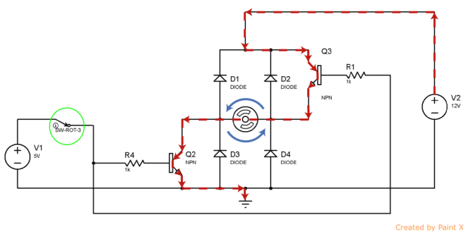
If the green switch takes the other position, the resistors feeded are R1 and R4, as shown in the image below. Current flows in the other direction thus the motor spins anticlockwise.
And this is the story of how this little Arduino component does its magic.
This is the first Integrated Circuit we encounter, and it was interesting to learn how it worked on the inside. On the same site where we got all this information, there was a scheme to build an H-bridge with Arduino at a large scale. We might post another video later if we find the time to build it ourselves.
Briefly, as it is explained in the Starter’s book the H-Bridge polarizes the voltage applied to make the motor turn one way or another.
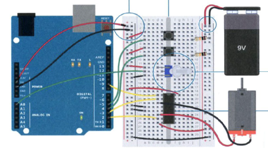
Back to the project, the book integrates the motor into a cardboard-made-zoetrope, which can be built following these instructions.
There are two button switches: one will serve to either turn the motor on or off and the other to switch the direction in which the motor is spinning. The potentiometer will regulate the speed. As before, we will need a 9V battery to feed the motor.
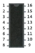
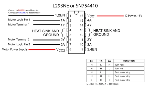
The H-Bridge has many pins that we will try to explain shortly.
This IC allows us to connect and control two different motors, as it has one bridge on each side (it is kind of antisymmetric). The pins named EN enable or disable the motor depending on the entering voltage. Each pin enables the motor connected to the terminals separated by commas. The Logic pins denoted by A make the motor turn left or right, or anything indicated by the table. The motor terminals are plugged into the Y pins. The middle pins serve as ground and the two pins left are for the power supply.
This is the code we used:
constintcontrolPin1=2;// the control pins will carry the
logic - direction to turn and applied to the H-BridgeconstintcontrolPin2=3;constintenablePin=9;// attached to the pin ENconstintdirectionSwitchPin=4;// 4 and 5 carry the values
of buttonSwitchesconstintonOffSwitchStateSwitchPin=5;constintpotPin=A5;// analogic signal, because it is a
potentiometer delivering continuous valuesintonOffSwitchState=0;intpreviousOnOffSwitchState=0;intdirectionSwitchState=0;intpreviousDirectionSwitchState=0;intmotorEnabled=0;intmotorSpeed=0;intmotorDirection=1;
voidsetup(){pinMode(directionSwitchPin,INPUT);pinMode(onOffSwitchStateSwitchPin,INPUT);pinMode(controlPin1,OUTPUT);pinMode(controlPin2,OUTPUT);pinMode(enablePin,OUTPUT);digitalWrite(enablePin,LOW);// the motor initializes at OFF}
voidloop(){onOffSwitchState=digitalRead(onOffSwitchStateSwitchPin);delay(1);directionSwitchState=digitalRead(directionSwitchPin);motorSpeed=analogRead(potPin)/4;if(onOffSwitchState!=previousOnOffSwitchState){// this
part allows the user to have the motor spin without having to
hold the button itself. Otherwise we should keep pressing the
button switch to turn the motor. if(onOffSwitchState==HIGH){// if the user presses the
button, the state changes. Otherwise, it remains unchanged.motorEnabled=!motorEnabled;}}if(directionSwitchState!=previousDirectionSwitchState){// analagous to OnOffSwitchStateif(directionSwitchState==HIGH){motorDirection=!motorDirection;}}if(motorDirection==1){// If the Direction is 1, turn left.digitalWrite(controlPin1,HIGH);digitalWrite(controlPin2,LOW);}else{// If the Direction is 0, turn right.digitalWrite(controlPin1,LOW);digitalWrite(controlPin2,HIGH);}if(motorEnabled==1){// If the motor should be enabled,
set EN to HIGH and the motorSpeed indicated by the
PotentiometeranalogWrite(enablePin,motorSpeed);}else{analogWrite(enablePin,0);// If the motor is turned Off,
set EN to LOW}previousDirectionSwitchState=directionSwitchState;//
These lines are very important to keep the current state!previousOnOffSwitchState=onOffSwitchState;}
The end result looks like this:
We had some troubles holding the motor correctly, because the wires made a poor contact sometimes. Later we had to sold the wires (for a second time) to the motor, as it pulled off. At a few moments in the video one can observe (especially hear) that the motor had problems to start spinning, particularly at low speeds. We found the project to be fun in a technical sense, but discontented with the presentation we set the motor in another gears left at home.
In this project, we made a motorized pinwheel. In other words, we wanted a motor to spin. The first issue we had to deal with was that the motor included in the Starter Kit needed more current and voltage than the maximum dispensable by the Arduino’s output pins. To solve it, we used a battery of 9V.
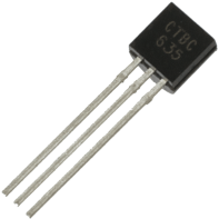
Another point was that we had to control the battery and the motor (high voltage) with low voltage (outputs from the Arduino’s pins). In order to achieve it, we needed to use a new element: a transistor. A transistor consists in three “parts”, each one connected to the protoboard: the gate, the source and the drain. When low voltage (the one that provides Arduino’s pins) hits the gate, it closes the circuit between the source and the drain allowing you to turn on motors, batteries… and control them.
Now you can see a picture of a transistor:
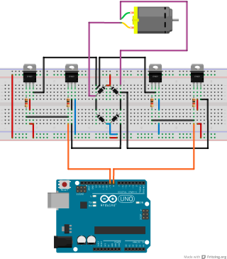
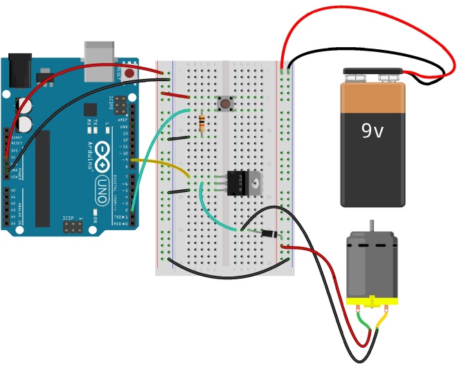
And here, there’s a picture of how we built the circuit:
As you can see there’s a black diode in parallel with the motor. This is because when the motor receives electricity, a magnetic field is generated. In consequence, voltage is created in the opposite direction that is conducted to the motor. It is called back voltage. When you turn off the power supply and the motor is spinning, owing to the inertia it will continue moving for a while. Then the back voltage becomes a problem and can damage the circuit. The diode avoids this situation protecting the circuit.
The code used has been:
//Introducing the constants of the switch and the motorconstintswitchPin=2;constintmotorPin=9;intswitchState=0;voidsetup(){//Selecting as an input and output the switch and the motorpinMode(switchPin,INPUT);pinMode(motorPin,OUTPUT);}voidloop(){//Reading if the switch has been pushedswitchState=digitalRead(switchPin);if(switchState==HIGH){//If the switch has been pushed make the motor spindigitalWrite(motorPin,HIGH);}else{//If the switch hasn't been pushed don't make the motor spindigitalWrite(motorPin,LOW);}}
To make it funnier, we used a circular coloured paper and it looked this way!
P.S. We have to say we had several problems with the wires of the motor. We had to weld each wire once (the positive and the negative) because the soldering had broken. Be careful with it, at the beginning it was hard to realize it was broken!
Welcome to our new post. On this project, a digital hourglass is being built. As you might have deduced, the sand would be replaced by some LEDs and a tilt switch (also known as mercury switch) will detect when the hourglass turns.
During this project you will learn about tilt switches and how to use them. In addition, we are using the millis() function , which is going to replace delay(). Long variables are being introduced too.
The first step is to understand what a tilt switch is and when we are going to use it. It is quite similar to a normal switch, and as a digital input has two levels (end and power). As it has been mentioned, this kind of switch detect when is being rotated. This is because there is a small metal ball inside which make contact and close the circuit when tilting the switch in the appropriate direction.
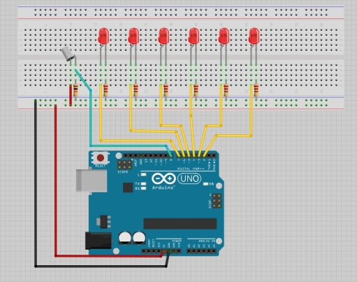
Our hourglass is counting 30 seconds lighting a new LED every five seconds. In order to advice when time is about to finish the LEDs start blinking. Is to notice that the project proposed by the Arduino Started Kit presents some differences.
To create this project you will need six LEDs, a tilt switch, one 10k Ohms and six 220 Ohms resistances.
You should have noticed that all the outputs and inputs are digital. There is no specific difficult on mounting de circuit. Nevertheless, the following image will help you to make it properly. If you have any doubt, don’t hesitate to write a comment. Our team would be grateful to help you.
As we have already mentioned, we are using the millis() function. Due to it doesn’t paralyze Arduino as delay() does. When delay() is being executed it is impossible to work with inputs and outputs at the same time. That’s why, in this project were time is quite important, we are avoiding this function.
As you might notice, in the following code long variables are being used. Until now, we have only used int, but in some cases they won’t be enough. An int variable is a number of 16 bit (it can storage decimal numbers from -32768 to 32767) while a long is 32 bit (can storage from -2147483648 to 2147483647). Knowing that Arduino counts 1000 times per minut using millis() and investing time on making the properly calculations you will discover that to create our hourglass a long variable is required. In fact, it is used an unsigned long which means that all the numbers are positive.
The code used and the video to show you the result is provided below.
constintPinInterruptor=8;//Initialising the constant variable for the tilt switch unsignedlongPreviousTime=0;//Using the unsigned long variable as expleined beforeintInterruptorState=0;//Initialtating variablesintPreviousStateInterruptor=0;intLed=2;//Variable used to count which LED will be the next on lightinglongTimeIntervalocadaLed=5000;//Every 5 secons a LED will lightintc=0;voidsetup(){for(intx=2;x<8;x++){pinMode(x,OUTPUT);//Stablishing all the LEDs as outputs}pinMode(PinInterruptor,INPUT);//Stablishing the switch as an input}voidloop(){unsignedlongActualTime=millis();//Knowing how long the program has been workingif(ActualTime-PreviousTime>TimeIntervalocadaLed){//Veryfing if has transcurred the required time to switvh on another LEDPreviousTime=ActualTime;digitalWrite(Led,HIGH);//Lighting a new LEDLed++;//Preparing to light the next oneif(Led==7){//In case that there is just one LED switch off advise by blinking all LEDs when the time is about to finish(2.5 seconds before)delay(2500);c=0;while(c<5){for(intx=2;x<8;x++){digitalWrite(x,LOW);}delay(500);for(intx=2;x<8;x++){digitalWrite(x,HIGH);}delay(500);c++;}}}InterruptorState=digitalRead(PinInterruptor);//Read sensor stateif(InterruptorState!=PreviousStateInterruptor){//Puting all variables at zero if the state has changedfor(intx=2;x<8;x++){digitalWrite(x,LOW);}Led=2;PreviousTime=ActualTime;}PreviousStateInterruptor=InterruptorState;//Stablishing the actual state as the previous one}
We hope you enjoy our particular version of the digital hourglass project.


 Notice that this scheme has 5 components: resistors, diodes, transistors, the motor and two voltage sources. In this circuit current doesn’t flow in any direction, because the switch highlighted in green is open. Current doesn’t move across the resistors that are connected to the transistor’s gate. The transistors, which act as ‘switches’ are left open. The diodes do not allow current to flow against the such drawn ‘arrow’, therefore it doesn’t matter whether the second voltage source is connected to the terminals: there is no path for current to take. Current cannot take its usual direction from the positive to the negative sign. The circuit is deactivated and the motor doesn’t move.